Darcy’s law can be applied to model reservoir flow systems. The simplest is steady-state radial flow (steady-state just means that the flow rate and pressure does not vary with time). Consider the figure below:
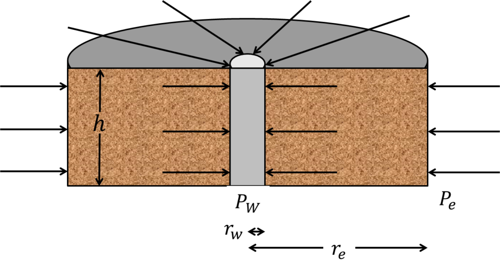
In vertical wells, we often assume a cylindrial drainage area as depicted in the figure above. The flow is directed from the reservoir boundary to the wellbore. To model flow scenario, we apply Darcy’s Law:
STEP_1: Write Down Darcy’s Equation and define the variables
(Note: I excluded the negative. You’ll see why later)
![\[ \frac{q}{A_c} =\frac{k}{u} \frac{dP}{dL} \]](https://topdogengineer.com/wp-content/ql-cache/quicklatex.com-0ad40c197cb186487390409f16075f9e_l3.png "Rendered by QuickLaTeX.com")
where:
![\[ {A_c} =2\pi rh \]](https://topdogengineer.com/wp-content/ql-cache/quicklatex.com-f5f1171432ad907260b5654dcabf6e62_l3.png "Rendered by QuickLaTeX.com")
For a cylindrical flow area.
STEP 2: Integrate by separation of variables
![\[ \frac{q}{2\pi rh} = \frac{k}{u} \frac{dP}{dL} \]](https://topdogengineer.com/wp-content/ql-cache/quicklatex.com-e92c09da094db06bcad8e8469d33945f_l3.png "Rendered by QuickLaTeX.com")
![\[ \frac{q}{r}dr = \frac{2\pi hk}{u} {dP} \]](https://topdogengineer.com/wp-content/ql-cache/quicklatex.com-aa6d71bdaf024a75d855e6e3149e19b1_l3.png "Rendered by QuickLaTeX.com")
![\[ \int_{r_w}^{r_e}\frac{q}{r}dr = \frac{2\pi hk}{u} \int_{P_w}^{P_e}{dP} \]](https://topdogengineer.com/wp-content/ql-cache/quicklatex.com-7c514bec620d68a83b71659d28ac5f5f_l3.png "Rendered by QuickLaTeX.com")
![\[ q[\ln{r_e}-\ln{r_w}] = \frac{2\pi hk(P_e-P_w)}{u}\]](https://topdogengineer.com/wp-content/ql-cache/quicklatex.com-7589ac5577c53f102913c205f9efdffc_l3.png "Rendered by QuickLaTeX.com")
STEP 3: Write the final expression
![\[ \boxed{q = \frac{2\pi hk(P_e-P_w)}{u\ln{\frac{r_e}{r_w}}}}\]](https://topdogengineer.com/wp-content/ql-cache/quicklatex.com-99a67f17ac1af5753f25bc1686981790_l3.png "Rendered by QuickLaTeX.com")
By inspection (if you plug in some numbers), the negative sign is not needed because the flow rate will be positive, indicating that the fluid is flowing to the wellbore.