Back to: Structural Analyst
If one designs a mechanical component satisfying all strength criteria, the component can still fail due to a phenomena known as fatigue failure. Fatigue of a component occurs when a fluctuating load acts on it. When a fluctuating stress acts on a material, micro-cracks form. As the load continues to fluctuate, the micro-cracks grow, eventually leading to failure. In the next few posts, we will cover an applied example of fatigue analysis. We will perform fatigue analysis of a Gondola ski lift.
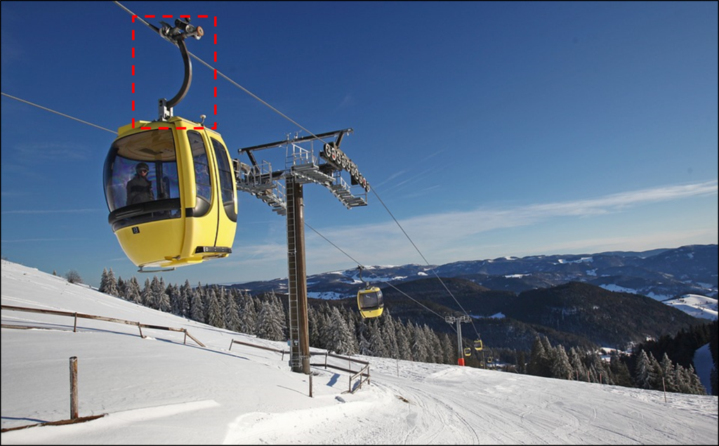
Your boss wants you to perform fatigue analysis on a gondola arm that guides the Gondola on a railway as illustrated below:

Your boss has specifically asked you to (1) identify the location of the worst case stress. He wants to peer review the results before you proceed further into the fatigue analysis. The data he provided is indicated below:
- A fully loaded gondola carries 15 people with an average weight of 200 lbs per person
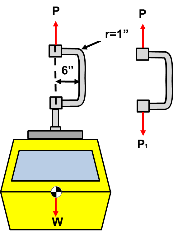
- The Gondola is supported by a bent arm tube with a radius of 1″
- The arm is offset by a distance of 6″ from the center of the gondola
- The unloaded gondola weighs 2000 lbf.
To simplify the problem, you decided to orient the bent arm so one could solve the problem by hand and get good approximate results to the arm shown in the image above. The first step to solving a fatigue problem is to perform a static analysis to find the internal forces at location of interest. We will step through the static analysis below:
STEP 1: Draw a free body diagram and determine the forces acting on the member of interest
The free body diagram of the entire system and gondola arm is illustrated below:

Applying the equations of equilibrium to the entire system the load P can be determined:

Applying the equations of equilibrium to the bent arm,

Since the bent arm is a two-force member, i.e. forces only acting at two points, the resulting forces have to be equal and opposite. Thus the above result makes sense.
STEP 2: Make a cut and determine the internal forces at the location of interest
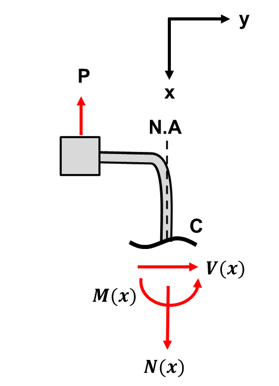
The worst case stress will occur in the upright portion of the bent member furthest from the applied load. A cut at this region is shown below:

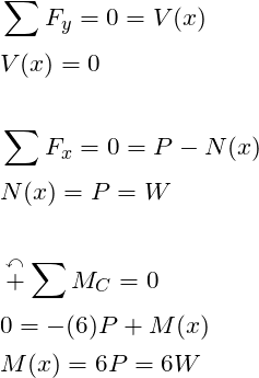
Notice that a neutral axis is defined along the cut member. Further, the cut is perpendicular to the neutral axis along every point of the neutral axis. Because these two criteria are satisfied, one can treat the vertical portion of the bent arm as a beam. In other-words if the neutral axis was curved, we couldn’t form an equation for the entire section. Using the equations of equilibrium, the shear, normal, and moment equations can be determined. The procedure is shown below:

From the analysis above, one can conclude the vertical portion of the bent arm is loaded axially by the normal force