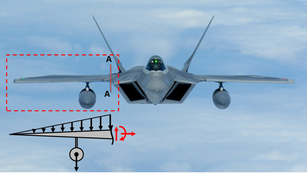
In college we focus on finding the internal loads of static systems. We rarely are asked to find the internal loads of a dynamic system. It may seem daunting at first and one may question where to start. However it is really simple and we actually build onto the static approach. Consider the following problem: Your a young engineer that has performed structural analysis using FEA of the aircraft wing of a F-22 fighter plane to see if it can safely hold a newly proposed ballistic missle. Your asked to validate the results of the FEA analysis by determining the reaction forces at the base of the wing, where you expect the highest stress loads to be. You evaluate the aircraft at a 9G upward inertial loading condition. How would one do this?? Let me show you one approach. The figure below illustrates the component being analyzed on the F-22:
We will assume the following data:
- The wing weighs 1,250 lbf and the weight is triangularly distributed
- The weight of the missle is 625 lbf
- The wing length is 30 ft long
- The missle hangs 13 feet from the base of the wing.
- The aircraft experiences a 9G upward load
Now that we know the data we can proceed with the analysis.
STEP 1: Make a cut and draw a free body diagram with all the forces acting on the body
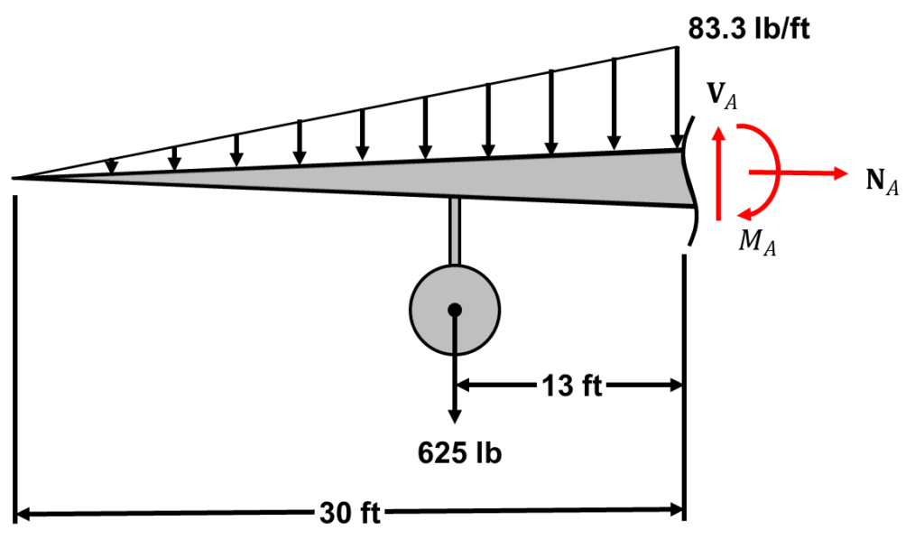
Note: Anytime you make a cut, you have to draw Normal (N), Shear (V), and Moment (M) internal forces period.
STEP 2: Determine the location of the center of gravity and the effective force

Determining the location of the center of gravity is critical because the inertia force always acts through the center of gravity of the body being analyzed. Further, because all the forces act vertically, we only need to determine the center of gravity along the x-axis. Because of this we are allowed to translate the missle weight vector up to the wing and treat this as a bending problem.
STEP 3: Draw two free body diagrams: (1) The force diagram and (2) an effective force diagram

The effective force diagram shows all the inertial loads acting on a body and no force vectors. This includes accelerations and angular accelerations. The force diagram shows all the external forces acting on the body. The two diagrams are equivalent to each other and is an illustrative application of Newton’s second law, i.e.  . We can treat this as a statics problem by subtracting the inertial load/effective forces to the the other side i.e.
  . By treating this as a statics problem, we can then determine the internal forces like we are familiar with in statics! If this were a statics problem, the effective force diagram would have nothing on it and newtons law would be
  .
.
STEP 4: Determine the reaction forces using the equations of equilibrium
For 2-D dynamic problems we always have 3 equations of equilibrium. In this case, we have three unknowns ( ,
,  , and
, and  ). We have three equations and 3 unknowns, thus this problem is determinate and we can solve for all the reaction forces.

There you have it! We were able to determine the internal forces at a specific location of a dynamics problem by extending our knowledge of Statics. This is a simplistic approach that only requires two additional steps compared to a traditional statics problem: (1) finding the location of the center of gravity and (2) drawing a effective force diagram. I hope you learned something and more is to come.