Thus far, we have applied fundamental formulas to determine the stresses in different structural members neglecting high stress regions. In reality, components contain shoulders, rounds, holes, grooves, ect. When such features are present, a highly localized stress region exists. An analyst/structural engineer needs to account for these features because in some cases, the stresses can be a quite a bit larger than stresses calculated by fundamental formulas. We will step through an example so that one can get comfortable for calculating stresses in high stress regions. Consider the loaded shaft illustrated below:

How would one calculate the maximum stress in the shaft taking into account stress concentrations?? It’s actually fairly simple. Let’s get started.
STEP 1: Draw a free body diagram and solve for the reaction forces
One always calculates the forces before the stresses, period… The free body diagram is already illustrated above so I will skip to determining the reaction forces with the following equations:

STEP 2: Draw shear and bending moment diagrams to find the worst case stress location
From the free body diagram one should be able to tell that the load at point B will be larger than the load at point C because the load is closer to point B. We can verify this with a shear and bending moment diagram.
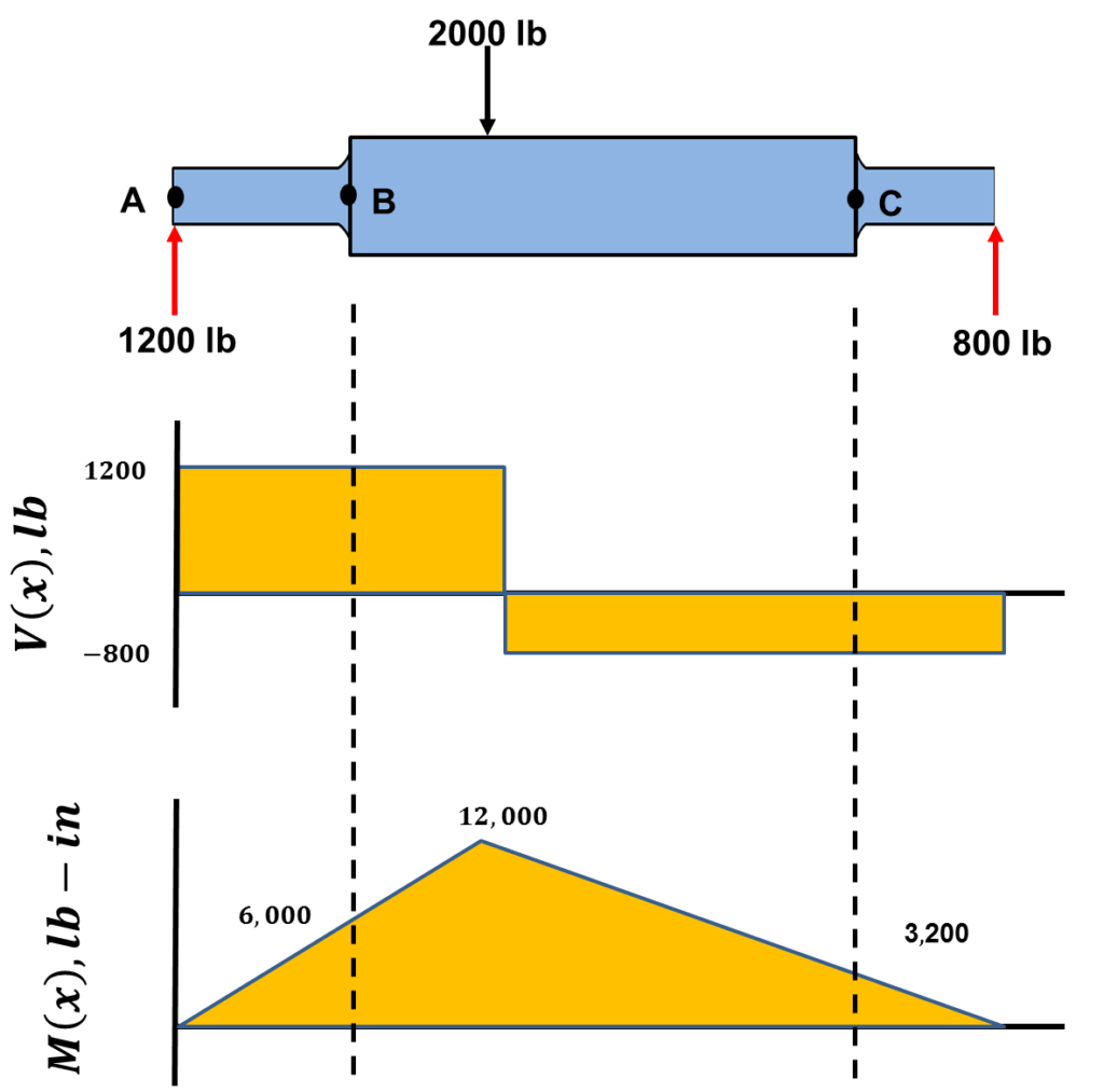
The bending moment diagram confirms that the moment at B is greater than the moment at C. How did one get the bending moment at these locations? Just remember that the area under the shear stress diagram is the bending moment. For example, the bending moment at fillet B and fillet C can be calculated the following way:

STEP 3: Determine the stress concentration factor at the fillet location using graphs.
Almost any book on mechanics of materials will have graphs to specifically calculate the stress concentration factor  for rounds, grooves, holes, ect.. To calculate the stress due to a stress concentration, one needs to calculate three values: (1) the nominal stress and (2) two ratios for a specific loading condition. These values and equations to get these values are shown on a stress concentration graph, so you do not need to remember them. An example of one is illustrated below:
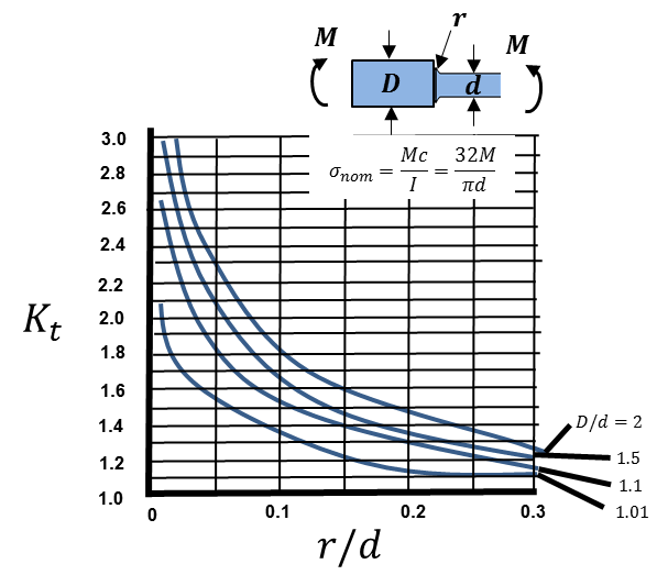
For our scenario one must evaluate the bending case. The graph illustrated above shows a range of stress concentration factors for fillets of a round shaft, which is what we want. From the graph one can see we need to calculate two values to determine the stress concentration factor. The values are calculated below:

Using the values above, one can approximate the stress concentration factor from the graphs. I got
 . Just remember, the stress concentration factor is a geometric property.
STEP 4: Determine the stress at the fillet
To calculate the stress at the fillet we use the following equation:
(1) 
First we must calculate the nominal stress (
 ) at point B. The equation is provided on the stress concentration graph.

We then can calculate the stress at the fillet from Equation (1) to be  .
.
There we have it! In summary, to calculate the stress due to a stress concentration factor, we pretty much follow the same rules we have followed previously, e.g. find the internal forces at the location of interest. All we do different is (1) use a graph to determine the stress concentration factor for our specific scenario and (2) multiply the stress concentration value by the nominal stress.