The stress analysis of a tapered or varying cross section beam is slightly different than a uniform beam when it comes to bending stress analysis. This is because the area moment of inertia varies along the length of the beam. However that is really the only difference. The same solid mechanics and statics fundamentals still apply and can be evaluated with simple hand calculations. Consider an end loaded tapered beam as illustrated below:
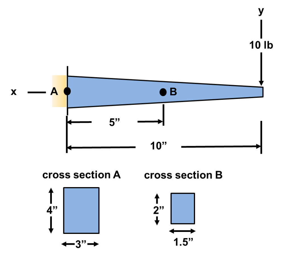
If one was asked to find the stresses at point A and point B at the following three locations (1) top of the beam, (2) middle of the beam, and (3) bottom of the beam, could one do it? Of course as we will see below:
STEP 1: Make a cut and determine the shear and bending moment equations:
If you recall we have solved for shear and bending moments previously for an end loaded cantilever beam. The same principles apply here so I’m going to skip to the answer. If one does this correctly, they should get the following equations:

STEP 2: Determine the shear and bending moments at the two locations:
We will need the shear and bending moments at the two locations to evaluate stresses. Using the equations developed in STEP 1 one gets the following results:

STEP 2: Determine the shear and bending moments at the two locations:
Because the cross sectional area varies across the beam one must calculate an area moment of inertia specific to the location being evaluated. The calculation for section A and B is illustrated below referencing the figure at the top of the post. Note the area moment of inertia for a rectangular cross section is
 .
. 
STEP 3: Determine the stresses due to bending:
Recall for a beam in bending, the stresses at the top, middle, and bottom of the beam are calculated with a certain set of equations. These equations and their locations are illustrated below. Further, the stress elements at the top, middle, and bottom of the beam is also shown:
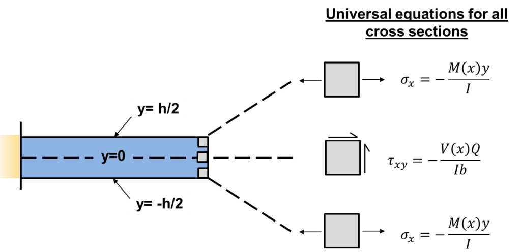
For a rectangular cross section, the shear stress at the middle of the beam is defined as  . The calculations for the stresses at the top, middle, and bottom of the tapered beam is illustrated below:


From the results above we can see that the top of the beam is in tension and the bottom of the beam is in compression at both locations, as we expected. Further, location B experiences the highest stresses. There we have it! One is able to apply fundamental equations for beams to a tapered beam. In summary, all one needs to remember is that the area moment of inertia is specific to the location on a beam. One should not fear an object that has varying cross section.
References: (1) Roark’s book on stress and strain (2) Strength of Materials Bansai