Anyone that has done finite element analysis has been exposed to stiffness matrices. Each term in a stiffness matrix represents the structures ability to resist deformations under different types of loads. Types of deformations that are considered include 1) nodal displacements and 2) nodal rotations if your talking about FEA. But the concept still applies to statics problems as well. The easiest way to interpret structural stiffness mathmatically is with the following expression:
(1) 
where  is structural stiffness,
  is a point load that causes a displacement
  , and
, and  is a moment that causes a rotation
  . Basically the smaller a material deflects, the stiffer it is. Now to get ones ahead around the concept of stiffness, we can derive expressions for stiffness using statics and mechanics of materials. We will use a cantilever beam as an example and derive two different stiffness expressions using the integration method: One for a point load and another for a bending moment . Consider the cantilever beam with a point load as shown below:

STEP 1: Draw an FBD and Make a Cut
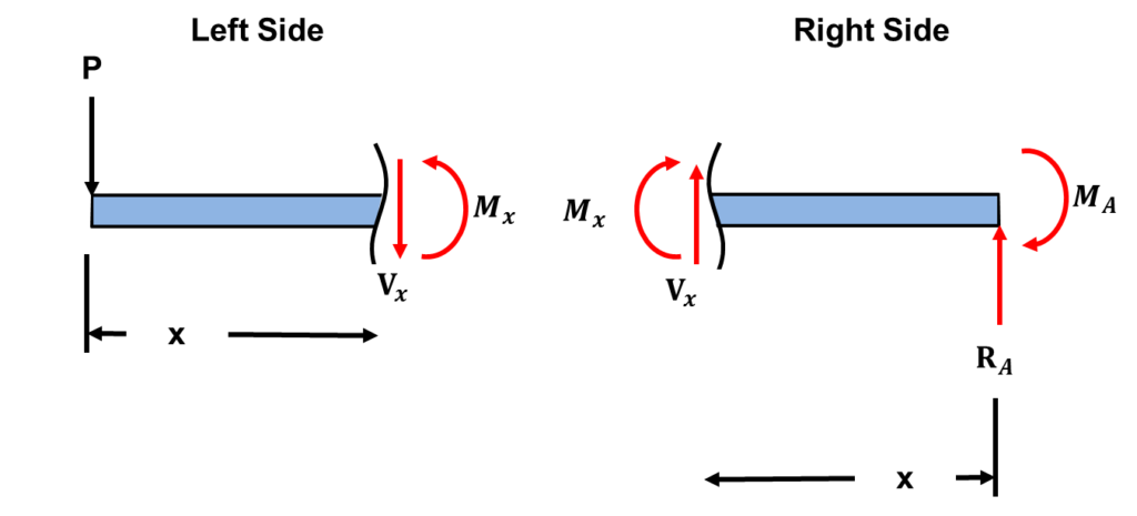
Because the left side includes less terms, we will solve for the bending moment and shear forces for the left side.
STEP 2: Solve for the bending moment equation using the equilibrium Equations

STEP 3: Integrate the moment equation twice to get deflection
Recall that the deflection of a beam is defined by the following differential equation:
(2) 
Substituting the derived moment equation and integrating the equation twice gives the following expressions:

STEP 4: Apply boundary conditions to get the deflection equation
To solve the equation for deflection, we need two boundary conditions since we have two constants generated from integrating. The boundary conditions can be visualized by the deflection curve of the beam as illustrated below:

At the fixed end of the beam, the slope is zero and the deflection is zero. Applying the boundary conditions, to the equations derived in STEP 3 we get the value of the constants as given by the following expressions:
![\begin{align*}\label{Step4}&[x=L,\frac{dy}{dx}=0]\\&EI(0) = \frac{1}{2}PL^2 + C_1\\&C_1= \frac{1}{2}PL^2\\\\&[x=L, y=0]\\&EI(0)= -\frac{1}{6}PL^3 +C_1L+C_2\\&C_2 = \frac{1}{6}PL^3 -C_1L\\&C_2 = \frac{1}{6}PL^3 -\frac{1}{2}PL^3\\&C_2 = -\frac{1}{3}PL^3\end{align*}](https://topdogengineer.com/wp-content/ql-cache/quicklatex.com-fabeb570f93e811389ed033f02a8711f_l3.png "Rendered by QuickLaTeX.com")
The final expression for the deflection across the cantilever beam is given by the following expression:

STEP 5: Evaluate the deflection at the end node of the beam and rearrange equation in terms of stiffness.
To determine stiffness, the max deflection is normally used. In the case of a cantilever beam, the max deflection occurs at the end of the beam. Using the equation derived in STEP 5 and evaluating at  , the max deflection is the following:

Recall that stiffness is defined as  . If we rearrange the equation above , we can determine the stiffness of the cantilever beam. The result is:
(3) 
That’s it!! We were able to apply our knowledge of solid mechanics and statics to derive the stiffness of an end loaded cantilver beam. In some cases, we deal with torque loads, i.e. moments. In this case we have to define stiffness as
 because one does not have a load . Consider a cantilever subject to a moment load:
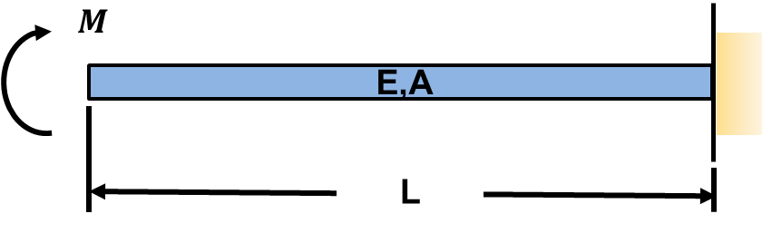
STEP 1: Draw an FBD and Make a Cut
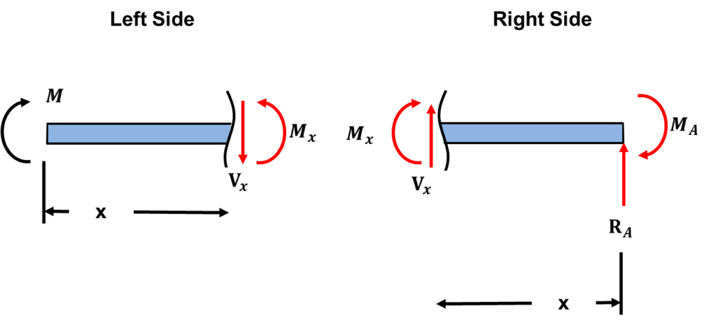
Because the left side includes less terms, we will solve for the bending moment for the left side.
STEP 2: Solve for the bending moment equation using the equilibrium Equations

STEP 3: Integrate the moment equation once to get slope
Recall that the deflection of a beam is defined by the following differential equation:
(4)
Substituting the derived moment equation and integrating the equation once gives the following expressions:

STEP 4: Apply boundary conditions to get the rotation/slope equation
To solve the equation for the slope, we need a single boundary condition since we have one constant generated from integrating. The boundary condition can be visualized by the deflection curve of the beam as illustrated below:

At the fixed end of the beam, the slope is zero. Applying the boundary conditions, to the equations derived in STEP 3 we get the value of the constants as given by the following expressions:
![\begin{align*}\label{Step4}&[x=L,\frac{dy}{dx}=0]\\&EI(0) = ML + C_1\\&C_1= -ML\end{align*}](https://topdogengineer.com/wp-content/ql-cache/quicklatex.com-70da30f30f1580d0be8041ce0f39f173_l3.png "Rendered by QuickLaTeX.com")
The final expression for the slope across the cantilever beam is given by the following expression:

STEP 5: Evaluate the slope at the end node of the beam and rearrange equation in terms of stiffness.
To determine stiffness, the maximum slope is normally used. In the case of a cantilever beam, the max deflection occurs at the end of the beam. Using the equation derived in STEP 5 and evaluating at , the max deflection is the following:

Recall that stiffness is defined as  . If we rearrange the equation above , we can determine the stiffness of the cantilever beam due to a moment load. The result is.
(5) 
We are done!! In finite element analysis textbooks, stiffness is defined abruptly with very little background on where the different terms of the matrix equation comes from. Here I have derived some stiffness equations from the fundamentals of statics and solid mechanics using methods engineers should be familiar with.